GOVERNING OF STEAM TURBINE
B) Governing Protection System:-
1.) LMW Turbine Protection System
- Speed rise up to 111 to 112%
- Speed rise up to 114 to 115% (Back up protection)
- Impermissible (beyond + 1.2mm and – 1.7 mm) axial shift of turbine rotor due to thrust pad wear.
- Lubrication oil pressure dropping to impermissible value (below 0.3 atg).
- Vacuum in condenser dropping to impermissible value (below 540 mm atg).
- Main steam and reheat steam temperature dropping to impermissible value (below 465 C).
- Drip level in high pressure heater rising to impermissible value.
- Operation of generator protection.
- Manual tripping of turbine by pressing the knob of turbine shut down switch.
- Governing control oil pressure failing to impermissible value (10 atg).
2.) Protection system elements
1.) Emergency governor
2.) Turbine shut down switch
3.) Protection Relay :
- Overspeed
- Vacuum below 540 mm Hg column
- Lub oil pr. Below 0.3 ata.
- MS temp. low (<3500 C)
- HP heater lever extra high
- Manual tripping
3.) Turbine Protective Devices
(A) Hydraulically Operated Devices
- Over Speeding
- Vaccum Failure.
- Thurst Bearing Failure.
(B) Protection Through Electrical Circuit
- Lubricating Oil Failure
- Generators Motoring
- Abnormal Generator Parameters.
(C) Through Operators Intervention
- Excessive Vibration
- Excessive Temperature Diffrentials.
- Abnormal Expansions.
- Abnormal Eccentricity.
(D) Automatic Unloading Gears
- Low Vacuum Unloading Gear.
- Low Steam Pressure Unloading Gear.
For (A), (B) & (C), tripping of the turbine is effected by automatic actuation of hydraulic or remote electrical tripping devices. (D) is achieved by features available with the hydraulic circuit with governing system.
4.) FUNCTIONAL DIVISIONS OF GOVERNING SYSTEM COMPONENTS
Main Components are:-
1.) Resetting Circuit
a) Resetting the Protective Devices
b) Resetting of HP & IP Stop Valves
2.) CONTROLLER
a) Regulating Opening of control valves
3.) Testing Circuit ( ATT à Automatic Turbine Testing )
4.) SAFETY CIRCUIT
a) Closure of Stop Valves
b) Temporary Closure of Control Valves
1.) COMPONENTS OF SAFETY CIRCUIT
- MAIN TRIP VALVE
- OVERSPEED TRIP DEVICE
- LOW VACUUM TRIP DEVICE
- THRUST BEARING TRIP DEVICE
- HAND TRIP DEVICE
- REMOTE SOLENOID TRIP
HP & IP Stop Valve Servo Motors
Actuators of CRH NRV & Extraction lines FCNRV
2.) COMPONENTS OF CONTROLLER
- PRIMARY OIL PUMP
- STARTUP AND LOAD LIMITING DEVICE
- HYDRAULIC AMPLIFIER
- ELECTRO HYDRAULIC CONVERTER
- CONTROL VALVE SERVO MOTOR
- PILOT VALVES AND FOLLOWUP PISTONS
3.) COMPONENTS OF ATT
- MAIN TRIP VALVE
- CHANGE OVER VALVE
- OVERSPEED TRIP TEST DEVICE
- LOW VACUUM TRIP TEST
- STOP VALVE TEST VALVE
- TEST SOLENOIDS
- RESET SOLENOIDS
MODE OF OPERATION
- SPEED DECREASING –
GOVERNOR SLEEVE-LEFT LOWER OIL FLOW MOVEMENT OF FOLLOW PILOT MOVT. OF FOLLOW PILOT TRANSMITTED TO DIFFRN. & INT. PILOT VALVE
- LARGE LOAD DUMP –
SUDDEN DROP IN PRESSURE IN THE OIL LINE DIFFERENT. IN ACTION ANTICIPATORY CLOSURE OF CV
- WHEN SYNCR. WITH GRID
SPEED IS CONTROLLED WITH THE MOVEMENT OF SLEEVE
OIL SUPPLY TO GOVERNING SYSTEM
HIGH PRESSURE CONTROL OIL (32 BAR)
POWER OIL TO CONTROL VALVE SERVO MOTOR
LOW PRESSURE CONTROL OIL (8 BAR)
FEEDS TO SAFETY CIRCUIT, ATT AND CONTROL CIRCUIT
LUBE OIL
FEEDS TO PRIMARY OIL PUMP FOR HYDRAULIC SPEED SENSING
Controller Features:-
- Load Controller ( PI Controller )
- Pressure Controller ( PI Controller )
- Speed Controller ( PD Controller )
Features of Load Controller
Features of Speed Controller
Features of Pressure Controller
5.) GENERATED FLUIDS AND THEIR FUNCTIONS
- START UP OIL
- AUXILIARY STARTUP OIL
- TRIP OIL
- AUXILIARY TRIP OIL
- SECONDARY OIL
- AUXILIARY SECONDARY OIL
- TEST OIL
- PRIMARY OIL
Governing Oil
1. START UP OIL
2. AUXILIARY STARTUP OIL
3. TRIP OIL
4. AUXILIARY TRIP OIL
5. SECONDARY OIL
6. AUXILIARY SECONDARY OIL
7. TEST OIL
8. PRIMARY OIL
Hydraulic Amplifier
Main Trip Device
Start up and Load Limiting Device
 Over Speed Trip device
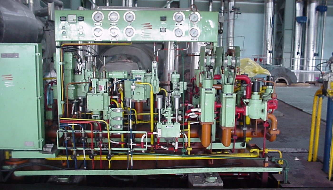
Photos:-


Very good write-up. I certainly appreciate this site. Keep it up!