Bearing Float of Steam Turbine
Thrust Bearing Float:-
- It is the total axial movement of the Rotors between the working and the Non working Pads of the Thrust Bearing.
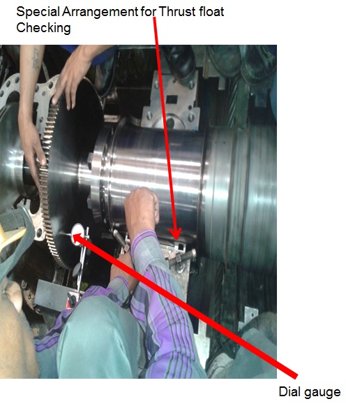
- It is measured by moving the rotors from the extreme end of the working pads to the extreme end of the Non working pads or vice versa Reading is measured by Dial Gauges .
- Its value varies from 0.35 mm to 0.60 mm depending upon the turbine design.
- Value less than the design value leads to Lubrication problem.
- Value more than the design value can lead to accelerated wearing of the Babbit pads.
- Any metal when exposed to high temperature will Expand. This axial movement is locked by means of thrust bearing pads which restricts the movement of the thrust collar either way. However we have to leave some gap between the rotating thrust collars and stationery thrust pads to allow rotation with minimum friction in oil film . This free movement of the thrust collar between the thrust pads is called as Bearing Float. It is in the range of 0.35mm to 0.6mm.
Thrust Bearing Float Procedure:-
Before taking Float reading we have to carry out the blue matching of the thrust pads of both sides. All the pads must have sufficient impressions.
- Place the dial Gauges on the thrust collar , bearing and yoke.
- Rotate the rotor by crane and by manual force press the whole rotor assembly towards one side of pads ( working or non working).
- Make the Dial positions zero.
- Again rotate the Rotor and displace the rotor assembly now to the opposite side of the earlier movement.
- Record the readings of the each Dial gauges.
Thrust Bearing Float Correction:-
- If the bearing Float is less then desired float can be achieved either by removing Babbitt material from the pads OR by adjusting Spacer thickness behind the collar containing non working pads. However normally first method is opted.
- If the bearing Float is more than the Spacer thickness is increased.
- The yoke movement should not be more than 0.03 mm . If it is more than this then necessary correction is required in the toothed locking rings.
Thrust Bearing Float Check List:-
- While putting the axial force on the rotor remember the force is to be released only when the rotor has been stopped completely.
- Before taking reading Ensure that the pads of the thrust bearing is considerably tight.
- Before doing any adjustment in the Spacer please ensure it is true on its face on both side and match with the surface plate before final insertion.
- The raised step of the each Thrust pad should also be made true with respect to Babbit surface. otherwise it can give faulty reading.
Thrust Bearing Float Protocal:-
| Floats:- Float is set to be 0.3 – 0.55 mm as standard. | |||||||||||||
| Active Pads in position Float Towards Non Active Side Without Non Active pads | Non-Active Pads in position Float Towards Active Side Without Active pads | Total float (Bump Float, Without Active 7 Non Active Pads) | Thrust Float | ||||||||||
| mm | 1.73 | 2.6 | 4.3 | 0.33 | |||||||||


