What Is CFB Technology
Contents:-
1. History
2. General Advantages
3. CFB System
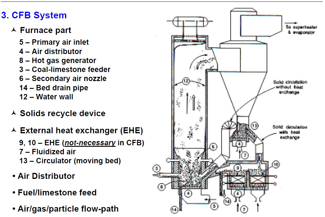
– Furnace
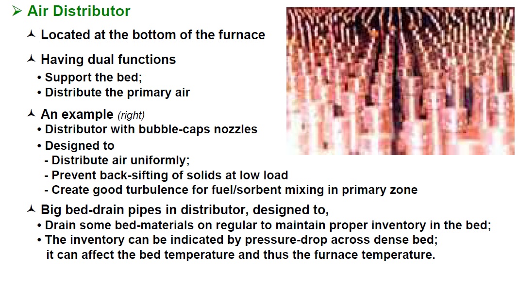
– Air Distributor
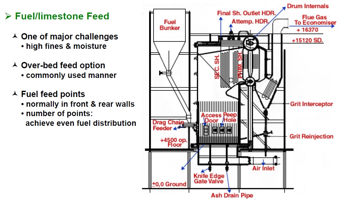
– Fuel/limestone feed
– Solids recycle device
– External heat exchanger (EHE)
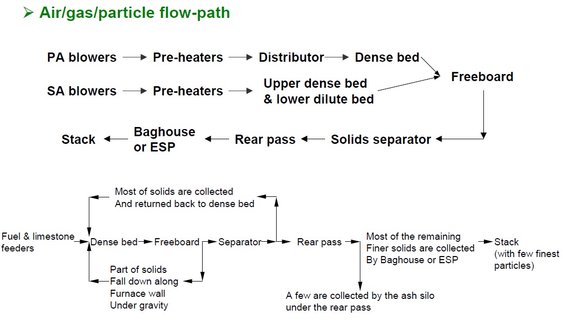
– Air/gas/particle flow-path
1. History
- less than 20 years old
- Modern and mature technology to burn coal and other solid fuels
- More than 400 CFB boilers in operation worldwide
- Unit capacity: from 5MW to 250MW (electricity)
- General description:
• Use fluidized bed principle;
• Crushed (6~12 mm) fuel and limestone are injected into the lower furnace. The particles are suspended in a stream of upwardly flowing air that enters the bottom of the furnace through air distribution nozzles;
• Balance of combustion air is admitted above the bottom of the furnace as secondary air;
• Combustion takes place at 815~925°C, with uniform combustion condition in chamber;
• Fine particle (< 450 microns) are elutriated upward in furnace with flue gas of 4~6 m/s.
Particles are then collected by the solids separators and circulated back into the furnace.
Individual particles may recycle anything from 10 to 50 times
• Particles’ circulation provides efficient heat transfer to furnace walls and longer residence
time for carbon and limestone utilization.
2. General Advantages
Fuel Flexibility
The relatively low furnace temperatures (815~925°C) are below ash softening temperature of nearly all fuels;
Therefore, furnace design is independent of ash characteristics
Low SO2 Emissions
Limestone is an effective sulfur sorbent in temperature range of 815~925 °C
SO2 removal efficiency: >95%
Low NOx Emissions
Very low NOx emission, thanks to
– Low furnace temperature
– Air staging to the furnace
High combustion efficiency (even for difficult-to-burn fuels)
Very long solids residence time in furnace due to re-circulation
Vigorous solids/gas mixing in furnace
These two compensate negative effect of low furnace temperature
3. CFB System
3.1 Furnace
Operating at velocities corresponding to pneumatic transportation regime
• CFB furnace is high, in order to allow for a long residence time of the gas;
• Furnace cross-section is selected based on flue gas superficial velocity.
Furnace enclosure is made of gas-tight membrane water-cooled walls
Refractory to protect against corrosion & erosion
• Thin layer of refractory on all lower furnace walls;
• In dense bed, an ultra high strength abrasion-resistant low cement alumina refractory of 16~25 mm thick is applied over a dense pin studded pattern.
Furnace temperature is precisely controlled by maintaining proper inventory
Combustion Air
• Primary air: through distributor into furnace bottom, typically 60~70% of total air
• Secondary air: introduced through over fire nozzles & material injection points into the top of lower dense bed, 30~40% of total air. Several levels.
• Primary zone: the region below the lower secondary air level.
– The primary zone has reduced cross section to provide good mixing and promote solids entrainment at low load;
– Startup burners, fuel fed points & secondary ash recycle points located.
Dense bed vs. Dilute bed (freeboard region)
• Dense bed: In the primary zone [~4.25 m/s];
– Design for uniform distribution & intensive mixing of PA & bed solids
– High mass-transfer rate provides intense combustion & sulfation;
– High heat capacity of the bed allows burning any kind of fuels;
– Sub-stoichiometric conditions there limit NOx formation;
– Special erosion-protection ways needed.
• Dilute bed: In the middle and upper furnace [~6 m/s], design for
– Used as a disengagement zone: most of material carried-over from bed can settle and return to the bed inside furnace
– Served as a post-combustion chamber: sufficient residence time for fuel burnout and sulfur capture
– Height required to burnout volatiles and to settle entrained particles
The former is often larger than the latter; so most of the entrained solids in freeboard region re-circulate within furnace
– High solid inventory for better heat transfer rates & sorbent reaction
Solids densities are relatively high (level of 10 kg/m3 gas): very good
for gas-solid reactions and for heat transfer
– Heat transfer surface of the enclosure walls
– Good mixing of secondary air and combustion products
• Transition between them is gradual.


