Variable effort Support
1.) Variable Effort Support
Variable effort supports are simple devices that allow a degree of flexibility in the supported equipment. They operate like a spring balance whereby an increase in load, will mean a corresponding change in compressed length in direct proportion to the spring constant.
Where: Deviation ( 0/0) = displacement x sprinq stiffness xl 00
Operating load
It is important that the hanger is fixed in the correct position; error at the erection stage can cause a imbalance of the load and make it virtually impossible to ‘balance’ the supporting system.
2.) Erection
2.1 Variable effort supports rely on the freedom of movement of the spring and it’s compression plate; lack of adequate protection during storage, rough handling and abuse will significantly reduce the ability of the support to perform.
2.2 The support should be carefully lifted into its designated position and secured using appropriately sized fixing bolts/pins.
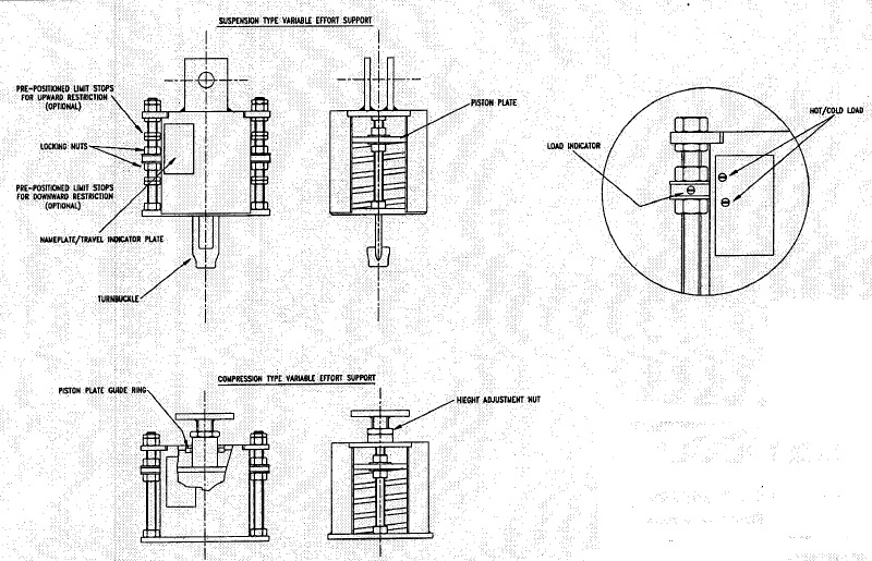
2.3 Attachment to the supported pipe work is made via the hanger rod and pipe clamp in the case of suspension type supports and via the plinth in the case of compression type supports. The pipe work should be accurately adjusted to its correct elevation using either the turnbuckle or the height adjustment nut.
2.4 If the pipe work is to be lagged with thermal insulation after the supports have been erected, the piston plate locking nuts, which are located above and below the piston plate on either side of the spring housing, should not be retracted from their original position i.e. in contact with the piston plate until lagging is complete.
2.5 If the pipe work is to be subject to hydrostatic testing, this must take place with the piston plate locking nuts, which are located below the piston plate on either side of the spring housing, still in their original position i.e. in contact with the piston plate. Standard spring supports
are designed to withstand an increased load during hydrostatic testing of up to twice the maximum load for the spring support.
2.6 Due to the variable nature of these devices and the need to support the pipe work at it’s optimum load when operating it is necessary to either over support or under support when installing a variable and in effect pre-stress the pipe work such that during thermal expansion it moves to a neutral state of stress.
2.7 Once satisfied that the pipe work is at its correct elevation the process of ‘balancing’ the system can commence. If the original assessment of weight distribution was correct, the pipe has been supplied to the nominal weight, valves and lagging are at their theoretical weight and all the supports are in their correct position then it is simply a case of undoing the locking nuts. However this is rarely the ground reality.
2.8 The process of balancing the supporting system is very much an iterative one, adjustment to one support may manifest in a change at another two or three positions away. It is best to work between fixed support positions or terminal points and work towards the centre where the piping is most flexible.
2.9 To determine whether a support is in balance or not it is necessary to observe the piston plate locking nuts found on threaded rods running the full length of the spring canister with the piston plate sandwiched between each pair. For balance these nuts should all be relatively free to be unwound away from the piston plate leaving the support in a static, self-supporting state. If this is the case for any particular support we strongly recommend that the nuts should be wound only 2mm away from the plate at this stage. This is simply a precaution to avoid the pipe work moving far away from it’s set position if subsequent supports are not truly balanced.
2.10 If the support is not in balance then either the lower (spring side) locking nut or the upper locking nut will offer significant resistance to turning. Should it be that the lower nut will not rotate then this signifies that the dead weight is greater than the effort being provided by the support. To compensate for this it is either necessary to lower the pipe slightly by releasing the turnbuckle or lowering the load pad, or by raising the pipe slightly on adjacent supports. The intention being to release the dead weight sufficiently to release the locking nuts. For base mounted supports the height adjustment nut is found immediately below the load plinth. Should the upper nut be difficult to rotate then the opposite should be applied. We recommend that this adjustment should not be carried out in total isolation; at least five consecutive supports should be worked on simultaneously to avoid introducing local stresses into the pipe work.
2.11 Subsequent supports should be balanced in the same way however it is necessary to continually check back to previous supports to ensure that the effect of changing supports towards the centre of the pipe run does not alter previously balanced supports. If this is the case then suitable adjustments should be made to overcome this and return these supports back to their correct position.
2.12 When all supports are floating, the locking nuts should be backed off fully to allow the system to operate correctly. (Provided there is no intension of carrying out any other activity like hydro test and the line is ready for charging).
2.13 Where the variable effort support incorporates a limit stop (Reaction force receiver), the lower locking nuts will be positioned at a distance from the spring compression plate as shown on the support detail drawing.
2.14 Prior to operating the plant we recommend that all supports are checked to ensure –
- The locking nuts are fully retracted.
- No debris has been allowed to fall into the support, especially in the spring housing.
- The support is free from visual damage and fixing bolts are firmly secured.
We also suggest that a cold survey is carried out to record the installed elevation of the pipe work and the indicated setting of the supports.
3.) Maintenance
3.1) Variable effort supports are designed to be maintenance free, however common sense should prevail; threaded items require greasing at intervals to suit the environment, periodic inspections are necessary to ensure the supports have not been damaged or obstructed by such items as temporary scaffolding, additional equipment or debris that may have fallen into the unit. Protective coatings should be periodically inspected and if necessary repaired.
3.2) Unfortunately due to the wide- ranging environments these devices are employed in, it is impossible to compile a fully comprehensive maintenance procedure. It should be remembered that variable effort supports are mechanisms and the health and longevity of the piping system depends on the reliable operation of the supports.
4.) Storage
Supports should be handled with care and stored in a dry and dust free environment, preferably off the floor and under cover. It may be necessary to use compressed air to clean the external & internal suspencess prior to commencing erection activities. We suggest that supports removed from their packing cases and protective covering only at the time of actual erection and not before.
5.) Drawing


Oh my goodness! a tremendous article dude. Thanks
you have got a fantastic weblog right here! would you like to make some invite posts on my blog?
you have brought up a very excellent points, regards for the post.
some really nice and utilitarian info on this site, besides I think the design has superb features.
I too conceive hence, perfectly pent post! .
I like this website its a master peace ! .
I am glad to be one of the visitants on this great site (:, thanks for posting.
keep up the wonderful work, I read few posts on this website and I believe that your web blog is real interesting and contains lots of superb information.
woh I am delighted to find this website through google.
You made some first rate points there. I appeared on the web for the problem and found most people will go along with together with your website.
woh I enjoy your posts, saved to my bookmarks! .
n incredible article dude.
Real fantastic information can be found on web site.
woh I love your blog posts, saved to bookmarks! .
Thank you for the auspicious writeup. It if truth be told was a leisure account it. Look advanced to far delivered agreeable from you! By the way, how could we keep up a correspondence?