Steam Turbine Vibrations & Diagnosis
1.) VIBRATION:-
Its manifestation in the form of amplitude of Oscillation, indicate some problem with the equipment e.g. Fever in a body.
The impact of high vibration usually are loss of integrity of components and associated generation loss because of forced outage either as a preventive measure or consequence of any failure due to high vibration/vice versa.
2.) VIBRATION STANDARDS:-
Class- I , II, III And IV
Presently, We follow ISO 10816-3 for vibration limit, it gives vibration limit in RMS value and we don’t have any standard which consider actual 0-P value for vibration limit So we will calculate vibration limit based on multiplication factor 1.41 (Which is applicable for standard sinusoidal timewave form). But in actual 0-P value no averaging of vibration values is considered so may be vibration value will be higher side in this unit for most of equipment.
3.) CAUSES, TYPE OF PROBLEMS AND CORRECTIVE ACTIONS:-
4.) VIBRATION MEASUREMENTS:-
5.) TURBINE VIBRATION ANALYSIS & DISGNOSIS:-
1.) INFORMATION/ DATA REQUIRED TO DIAGNOSE THE PROBLEM:-
- Frequency components causing change in amplitude of vibration (low frequency,1x, higher frequency etc.)
- Vector position (Phase and Amplitude) of 1x across different bearings in H,V and A directions, at different speeds.
- Bode plots, Cascade, Waterfall, Orbit plots, time waveform
- Process parameters correlation with load, speed, vacuum, etc.
- Turbine And Generator Bearing Drawing
- Critical Speed.
2.) LATEST DEVELOPMENTS-ONLINE DIAGNOSTIC SYSTEMS:-
3.) FEATURES:-
- Bar Graph
- Time waveform, Orbit
- Trend, Multi variable trend, XY plots
- Frequency spectrum,
- Acceptance region
- Bode, Water fall, Cascade
- Shaft average Centerline plot
4.) MCM/EXPERT SYSTEM WORKING:-
5.) INSTRUMENT USED FOR ANALYSIS:-
Equipment was used to carry out the analysis:
On-Line Shaft Vibration
Hardware : French Make OROS Model OR-36 – MOBIPACK 16 Channel Analyzer for measurement of “Shaft Vibration” from online vibration Monitor.
Software : OrbiGate
6.) TURBINE VIBRATION ANALYSIS AND DISGNOSTIC CASE STUDIES:-
A.) Case Study -1
B.) Case Study-2
A.) Case Study-1
A.1) Observations:- A unit was facing high vibrations, the vibration levels were reaching up to the trip levels in critical band on Generator bearings.
The shaft vibration are collected from Bentley Nevada Online Vibration Monitoring System.
A.2) Instrument used for Vibration:-
The following equipment was used to carry out the analysis:
On-Line Shaft Vibrations
Hardware : French Make OROS Model OR-36 – MOBIPACK 16 Channel Analyzer for measurement of “Shaft Vibration” from online vibration Monitor.
Software : OrbiGate
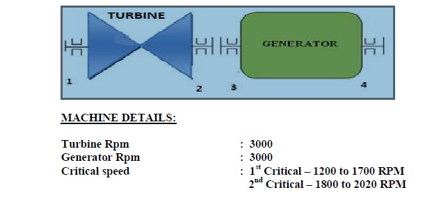
A.3) Machine Line Sketch:–
A.4) Observation & Analysis:-
After Detailed discussion about the machine behavioral pattern and it was understood that during Coasting down and Runup of the machine was exhibiting the following major anomaly:
(i) The Generator rear bearing was exhibiting high vibration amplification during RUN UP & COAST DOWN of the machine. The vibration levels are going up to the trip levels while passing critical speed zone.
(ii) The vibration levels at Generator rear bearing was going up to 193 microns Pk-Pk (2015 Rpm) during run-up & during coasting down vibration amplitudes was reaching up to 265 microns pk-pk at critical speed zone of the Generator Rotor. (Refer Run-up & Coast down Bode plots below)
(iii) Maximum shaft vibration amplitudes at Turbine rear bearing was recorded as 67/98 microns Pk-Pk. Spectrum & phase data reveals Unbalance of Turbine rotor.
(iv) Moderate Misalignment was indicating. Spectrum, Orbit was elliptical with eight shapes and also large phase difference could be observed across the coupling on Turbine and Generator bearings. Hence verify the alignment data with design values & correction to be done during available stoppage. (Below Gen-Front bearing orbit for
your reference)
A.5) Vibration Data of FSNL:-
ELATIVE SHAFT DISPLACEMENT VIBRATION (PK TO PK) IN MICRONS
A.6) Suggested Action Plan:-
(i) Recommended to verify the coupling run-out, male –female spigot blue matching.
(ii) During Run-up & Coasting down the Shaft vibration of Generator Rear bearing is observed to be higher side (up-to 265 microns Pk-Pk) And a same phenomenon was not found at Generator Front bearing.
Hence it is recommended to verify the following:-
Inspect the Generator End cover gland clearances for any partial or continuous rub which may lead to increase of critical speed vibrations.
Bearing interference, radial clearance, shaft run-out & also contact pattern of the bearing with respect to housing/ shaft to bearing bedding and also verify the shaft leveling.
Replace the Generator coupling hub with new hub as designers will take the critical speed vibration to get dampened during run-up & coasting down.
After above correction reassess the machine health condition.
B.) Case Study-2
B.1) Objectives:-
The objective of the study is to ascertain extent of influence of TG Foundation on the Machine Vibrations.
B.2) Observations:- High Vibration Problem in Turbine due to Influence of TG Foundation.
Following Observations:-
i. Visual inspection revealed that TG Foundation Columns are not separated from the Floor (FFL). This influences vibration characteristics of the columns as it results in free column height. Further it was also noticed that some ad-hoc modifications were done to TG Foundation (providing steel beams at around mid column heights on Generator side columns as well as one beam on Turbine side columns) but it did not give any relief to high vibrations.
ii. Further it was also noticed that cooler walls are also firmly attached to TG columns. This also results in influencing column natural frequencies.
iii. High vibrations of TG foundation appears to be on account of Foundation interaction with machine for which natural frequencies of columns are very much responsible.
iv. After one column was provided a clear separation from FFL, it resulted in some reduction of the vibration levels (measurements conducted then and there). The report provides a glance to the column behavior.
v. Further, misalignment is also noticed at Gen Front Bearing. It is recommended to get help from Mechanical Experts to overcome this issue.
vi. It is recommended that Cooler walls be separated from the columns. Also the steel beams that are provided to stiffen the columns of the TG Foundation, need to be removed.
vii. It is expected that the above recommendations would result in reduction of the vibration of the machine as well of the foundation.
viii. In case the problem still persists, it may be essential to first analyze the TG foundation for its dynamic behavior and then attempt changes to bring down the vibration levels.
B.3) TG Foundation – Schematic Plan View:-
B.4) VIBRATION PICK-UP LOCATIONS:-
Planning of Vibration Measurements on TG Foundation
1. Vibrations are recorded using SCL’s instrument Vibexpert that has FFT capability.
2. Since SCL vibration probe is uniaxial D-CAD has also used its own vibration Tester
Fluke 810 to record the machine vibrations as well as column vibrations.
3. Since vibration probe is magnetic, MS washers have been pasted throughout the
TG Foundation i.e. on all the Columns, at top deck and at FFL.
4. These washers are glued to foundation with chemical glue.
5. These washers become pick up points for magnetic probe.
6. In order to record vibrations at top deck in transverse and axial directions, MS
angle pieces were also pasted on the top deck with the chemical glue.
Schematic top deck plan with pickup location is shown as under:-
TOP DECK PLAN Showing Pick up locations (#1 to 24)
B.5) MACHINE VIBRATIONS:-
B.6) MACHINE VIBARTIONS RECORDED WITH VIBRATION TESTER FLUKE 810:-
B.7) TOP DECK VIBRATIONS:-
B.9) COLUMN VIBRATIONS:-
B.10) COLUMN VIBARTIONS RECORDED WITH VIBRATION TESTER FLUKE 810:-
B.11) FLOOR (FFL) VIBRATIONS:-
B.12) OBSERVATIONS:
• It is observed that there are 4 tie beams inserted in between the columns under generator side and one tie beam on Turbine side at mid column height.
• It is also noted that there is no airgap between columns and Floor at FFL
• Further walls of Cooler are connected to the generator side columns whereas as per drawing there is a clear gap of about 40 mm Vibration levels at Foundation and Machine.
1. Vibration levels at top deck level:
i. Vertical Vibrations are higher than Horizontal (transverse) as well as Axial vibrations.
ii. Vertical Vibrations show increasing trend from Turbine to Generator side.
iii. Vertical vibration at top deck shows increasing trend from turbine to Generator side.
iv. Horizontal vibration at top deck show increasing trend from Turbine to Generator.
All values are much less than allowable. It is generally noticed that amplitudes on turbine side are lower than those on Gen Side.
2. Vibration levels at Columns:
i. For a healthy foundation, vibrations should show diminishing trend from top of the column to bottom of column. In the present case vibration levels are more at column mid height level. Even velocity values at col middle are higher than those at top and bottom. This is not a healthy trend. Further velocity levels are 3 mm/s to 5 mm/s. This is on the higher side.
ii. It was noticed that vibrations show reduction after Column Separation from FFL (it was done at one column). iii. Overall column vibrations are higher as these should be less than those at top deck levels.
iv. Since vibrations at column middle are higher than those at top & bottom, it indicates that 1st bending mode of column is getting excited. It would therefore need further investigations.
v. It is noticed that Axial vibrations are generally higher than transverse vibrations.
This again points out to basic design of foundation from dynamic considerations
3. Vibrations at Floor Level (FFL):
i. Vibration levels at FFL are very small. That is a good sign.
4. Vibration levels at Machine:
i. Axial Vibrations on Gen NDE Bearing are much higher than acceptable level. At DE side, these are within in limit.
ii. Vertical vibrations at Generator DE bearings indicates predominance of 2X component. This indicates that there is need to check the machine for misalignment.
B.13) RECOMMENDATIONS:-
1. Vibration measurements indicate that under the present condition, the influence of TG foundation on machine vibration is significant.
2. Further, since all columns on Generator side are constrained in one way or the other, columns are not free to vibrate at their own natural frequency. This influences foundation vibrations significantly.
3. In view of the high vibrations experienced on generator side, and the fact that Dynamic design of the foundation is not available, it is suggested that:
i. All Columns to be isolated from FFL by an air gap of about 50 mm.
ii. Air cooler walls that are attached to Generator side columns need to be detached from the columns.
iii. The steel beams that are attached to all the four Gen side columns should preferably be removed and columns left free to vibrate.
iv. Steel Beam attached on Turbine side column should also be detached.
v. It is anticipated that with the above rectifications, vibration levels on the generator side should come down.
vi. Expert opinion from Mechanical Vibration specialists should be taken to resort to better balancing that will help reduce the vibration levels.
vii. In case vibration levels still persist, it would be desirable to carry out dynamic analysis of the TG foundation aided with further testing to arrive at plausible solution.


