Steam Turbine Alignments
1.) Turbine Alignments:-
After the bearings checking and replacement of any faulty bearing if any , with the spare one the next activity is the Alignment. Alignment means to make the two shafts coaxial i.e. radially and axially the shafts to be joined together should be in line. However due to many reasons which are as follows the shafts are given intentional angular misalignment in Top- Bottom axial reading.
- Bearing oil rise
- The deflection due to vacuum pull
- Hot well water effect
- Bearing temperature effect
- Flexibility of the bearing supports
- Bearing loading
- Spherical seating of the Bearing.
Alignment is carried out in RADIAL and AXIAL Planes
B.) Alignment Procedure:-
- Alignment readings are taken at four positions at 12,3,6,9,12 O clock position by rotating the couplings together.
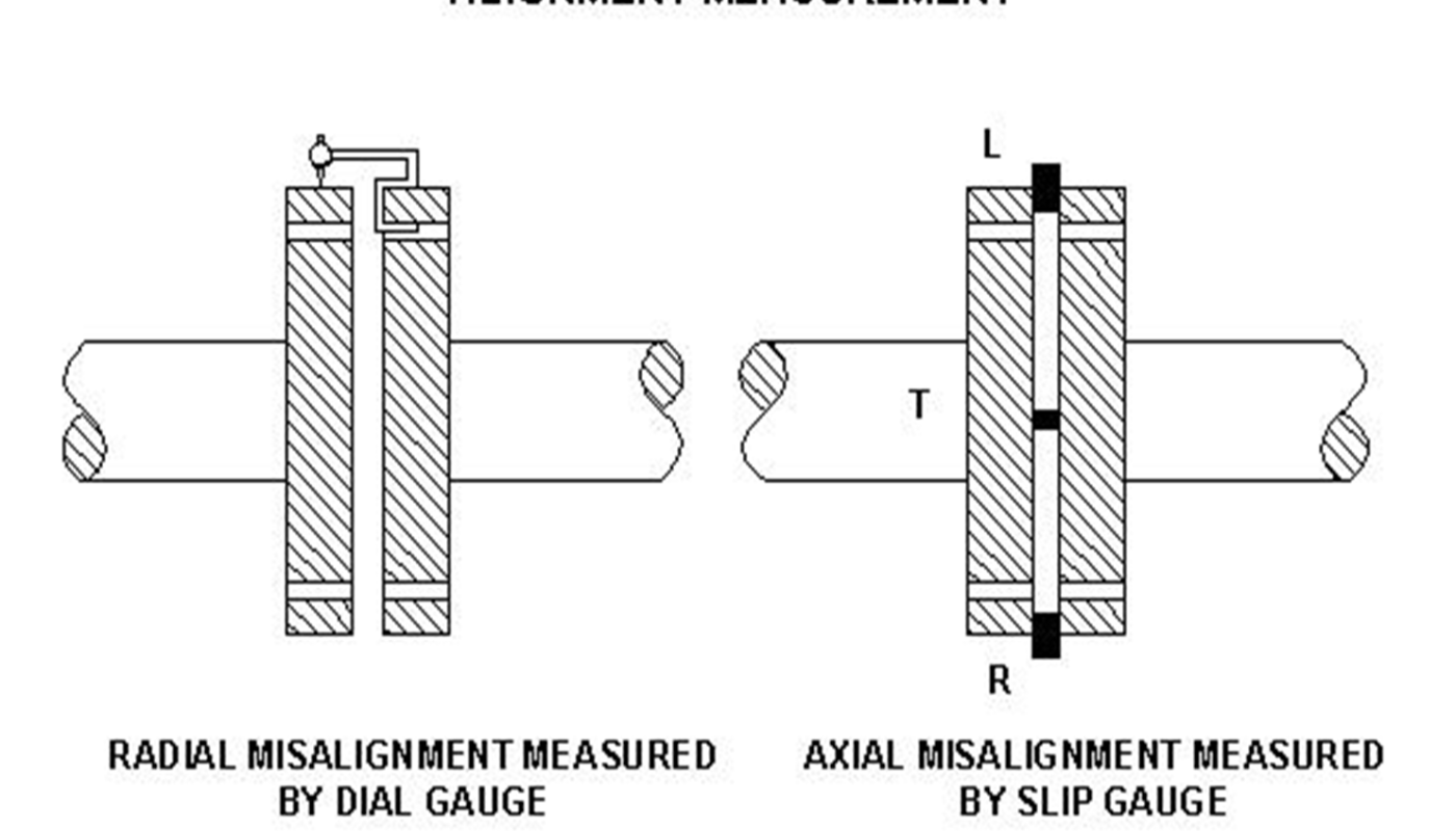
- Readings for Radial alignment is measured by means of dial Gauges and for axial alignment is measured by means of SLIP gauges. Put a stopper at convenient location to arrest the axial movement of the Rotor while rotation.
- Readings for Radial Alignment is taken by Dial Gauges at four locations.
- Readings for axial alignment i.e. the gap between the couplings is taken by the means of the slip Gauges at four location of couplings ie L,R,T,B each at four position of clock. Axial reading is averaged for four position of the Coupling locations.
- Attach a dial gauge to the one half of the coupling with pointer touching vertically on the other coupling at the 12 O clock position . Mark the couplings by paint/permanent marker to have common reference for measuring error free reading.
- Set the dial gauge reading to zero and also record the gap between the couplings at 12, 3, 9 ‘O’ clock position by means of the slip gauges.
- Rotate both the shaft together by a quarter (90deg) coupled with a loose bolt. Realign the couplings at the same reference . Record reading of the dial gauge and slip gauge reading again at 12, 3, 9 ‘O’ clock position.
- Repeat above procedure by rotating both the shafts together by Quarter each till the original position is restored.
- Radial Misalignment is directly indicated by the dial Gauge readings. For axial Readings the readings at each Clock position is averaged and then calculated for getting the axial misalignment. The axial reading at bottom is taken as ( L+R)-B
C.) Precautions during alignment:-
1. Always Ensure Bedding of the rotor with the bearing.
- During alignment process for IP-LP and LP-GEN coupling , condenser is to be kept on springs and water filled upto the tubenest level. During the final correction/ checking place LPT top half in position and tighten intermittently
- Always take readings for two sets.
- Best compromise between alignment and slope is to be achieved with priority for alignment.
- Always refer to the Dismantling readings of Alignment , Seal Bore and Slope during the process of alignment.
D.) Alignment deemed to be over :-
- If the readings obtained are as per design values
- Readings obtained in two consecutive sets are appx. Identical
- Check whether readings of L+R = T+B . If difference is there then readings are not proper.
- Ensure the final radial position of couplings is same as of set datum initially. If it is more than 0.01 mm then retake the reading.
E.) Correction after Alignment :-
If the alignment readings are not achieved then necessary corrections is achieved by adjusting shims in the three no bottom pads of the bearing, keeping into account of the SLOPE and SEAL BORE Reading.
F.) Check List of Alignment :-
- Always take readings for two sets.
- Best compromise between alignment and slope is to be achieved with priority for alignment.
- Always refer to the Dismantling readings of Alignment , Seal Bore and Slope during the process of alignment.
G.) Alignment Protocol:-
H.) Sequence of Alignment with Examples and Photos:-
Alignment of LP with Generator Rotor
1. The LP rotor is put in on the dummy bearing at Brg no. 2
2. Put brass handle inside the coupling bolt grooves
3. Rotate by lifting through crane.
4. Check by axial clearance filler gauges
5. Check radial clearance by dial gauges.
6. Check seal bore clearance using inside micrometer.
7. The HIP rotor is put in on the dummy bearing at Brg no. 2
8. Put brass handle inside the coupling bolt grooves
9. Rotate by lifting through crane.
10. Check by axial clearance filler gauges
11. Check radial clearance by dial gauges.
12. Check seal bore clearance using inside micrometer.
Alignment of LP with Generator Rotor
Correction in bearing as per alignment reading of LP & Gen Coupling then placing it back in housing.
Alignment of HIP & LP turbine rotor
Alignment of HIP Rotor with LP rotor
Lifting of LP rotor after aligning HIP rotor & placed in stand


