GOVERNING OF STEAM TURBINE
A) Governing/Regulation System ELEMENTS
- Speed governor
- Follow pilot
- Summation pilot
- Intermediate pilot
- Control valve servomotor
- Load/speed control pilot valve
- Load limiter
- Differentiator
- Electro-hydraulic transducer
- Speeder gear
- ISPUG(in 210 MW only)
Basic Elements Of A Governing System
1.) Speed Governor:-
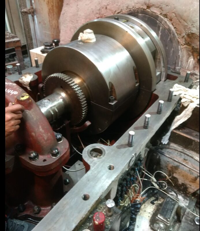
- MOUNTED ON MOP SHAFT & COUPLED WITH GEAR COUPLING
2.) Pilot Valve
Speed Governor Pilot Valve
2.) FOLLOW PILOT
- FOLLOWS MOVEMENT OF GOVERNOR SLEEVE
- ACTUATE SUMMATION PILOT VALVE
3.) SUMMATION PILOT
- RECIEVES SIGNAL FROM FOLLOW PILOT & LOAD/SPEED CONTROL PILOT VALVE THROUGH LEVER
- ACTUATE DIFFERENTIATOR & INTERMEDIATE PILOT VALVE
4.) Intermediate Pilot Valve
5.) Control Valve Servomotor CVSM
6.) LOAD/SPEED CONTROL PILOT
- CONVERTS MECH. SIGNAL FROM SPEEDER GEAR INTO HYDRAULLIC SIGNALS TO EMERG. GOVERNOR PILOT VALVE,ES VALVE SERVOMOTOR & IV SERVOMOTOR.
- ACTUATES SUMMATION PILOT VALVE THROUGH LEVER.
7.) Load limiter
8.) Differentiator
- Senses acceleration
- Receives impulse from summation pilot
- Cuts in –acceleration <=50% of rated load
- RESULT- closure of CV through intermediate pilot valve & CV servomotor
9.) Electro hydraulic Transducer
10.) Speeder gear
- 4.6 mm Interceptor valve begin to open
- 5.9 mm Interceptor valves fully open.
- 5.5 mm Emergency stop valve begin to open 6.65 mm Emergency stop valves fully open.
- 9.6 mm IP Turbine and HP Turbine Control valves beings to open.
- 12.8 mm All control valves fully open.
- Speed Governors are fitted with stops which limit the speed range above and below which they operate. The normal operating range is ± 6% of the nominal speed. Within this range the speed may be controlled by an operator making an adjustment to the relationship between the radius of the governor weights and the position of the governor weights. The adjusting gear known as speeder gear acts in parallel with the speed governor. After an initial run up the speeder gear is used to bring the machine to rated speed before synchronization. After the machine is synchronized the speeder gear controls its power output. In electrical governing system function of speeder gear is achieved by means of a motor driven potentiometer. As the speeder gear setting is represented by a voltage that is added to the electrical speed governor signal.
Characteristics
11.) ISPUG
- INITIAL STEAM PRESSURE UNLOADING GEAR
- REDUCES LOAD ON TURBINE IN CASE THE INITIAL STEAM PRESSURE FALLS BELOW 90% + 2%
- ELEMENTS OF ISPUG:
- CASING –HOUSES LINER & PILOT SPOOL
- LINER
- PILOT SPOOL –COUPLED TO ACTUATOER
- ACTUATOR –RECIEVES SIGNAL FROM PR. TRANSMITTER & ACTUATES PILOT SPOOL TO ROTATE IT INTO DESIRED DIRECTION THROUGH COUPLING.
Other Elements:-
1.) Emergency Governor
2.) Emergency Governor Pilot Valve
3.) Emergency Stop Valve
4.) Interceptor Valve


You have mentioned very interesting points! ps nice site.
I seriously love your site.. Excellent colors & theme. Did you build this website yourself? Please reply back as I’m trying to create my very own website and want to know where you got this from or exactly what the theme is called. Thanks!
yes definitely, i can make for you…. u can call me at +919251077570
or write
mananclass6@gmail.com
Simply desire to say your article is as amazing. The clearness in your post is simply cool and i could assume you’re an expert on this subject. Well with your permission allow me to grab your feed to keep up to date with forthcoming post. Thanks a million and please carry on the rewarding work.