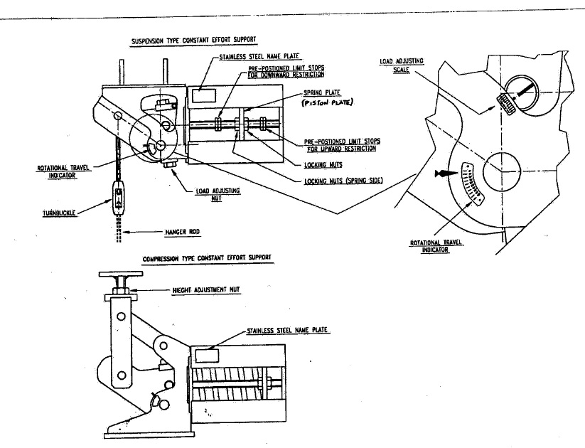
Constant effort Support
1.) Constant Effort Support:-
Constant effort supports deliver a constant supporting effort to the point of attachment of the supported part; it works like a counter-balance mechanism. It is important that the suspended load is reasonably close to the specified load in the drawings specifications.
Constant effort supports exhibit frictional and geometric variances from the nominal ‘set’ load; (Refer MSS-SP-58). This is usually defined as the ‘deviation’ and is a measure of the hysteresis of the load-displacement plot. The hysteresis of any particular support is usually within +1- 6% of the ‘set’s load. The significance of hysteresis is that for a given range of load the support will remain static at it’s set position; in order for the support to respond to changing conditions the tension generated in the hanger rod or the compression exerted on the supporting plinth must either increase or reduce by an amount slightly greater than the frictional resistance within the support. Therefore the ‘balancing’ of a support is a critical exercise if the support is to be set at its true mean load.
It is essential that the support is erected in the correct position; error at the erection stage can cause a re-distribution of the load and make it virtually impossible to ‘balance’ the supporting system, making one support over loaded and another under loaded.
2.) Storage
2.1 Supports should be handled with care and stored in a dry and dust free environment, preferably off the floor and under cover. It may be necessary to use compressed air to clean the external & internal spaces prior to commencing erection activities.
3.) Erection
3.1 Constant effort supports are mechanisms that rely on freedom of movement; lack of adequate protection during storage, rough handling and abuse will significantly reduce the constancy of the support and may cause malfunction of the bell cramk lever movement machanism.
3.2 The support should be carefully lifted into its nominated position and secured using appropriately sized fixing bolts/pins.
3.3 Attachment to the supported pipework is made via the turn-buckle /hanger rod and pipe clamp in the case of suspension type supports and via the load flange/plinth in the case of compression type supports. The pipework should be accurately adjusted to its correct elevation using either the turnbuckle or the height adjustment nut. NB. It is important that the pipe is suspended naturally; sagging or hogging pipework will impose false loads at the support positions.
3.4.1 If the pipe work is to be lagged with thermal insulation after the supports have been erected, the piston plate locking nuts which are located on both sides of the piston plate on either side of the spring housing should not be retracted from their original position i.e. in contact with the piston plate until lagging is complete.
3.5 If the pipe work is to be subjected to hydrostatic testing, this must take place with the piston plate locking nuts, which are located on the spring side of the piston plate on either side of the spring housing, still in their original position i.e. in the as despatched, factory set position. Standard spring supports are designed to withstand an increased load during hydrostatic testing of up to twice the maximum load for the spring support.
3.6 Once satisfied that the pipework is at its correct elevation the process of ‘balancing’ the system can commence. If the original assessment of weight distribution was correct; the pipe has been supplied to the nominal weight, valves and lagging/ insulation are at their theoretical weight and all the supports are in their correct position then it is simply a case of undoing the locking nuts.
3.7 The process of balancing the supporting system is very much an iterative one, adjustment to one support may manifest in a change at another two or three positions away. It is best to work between fixed support positions or terminal points and work towards the centre where the piping is most flexible.
3.8 To determine whether a support is in balance or not it is necessary to observe the spring compression plate locking nuts found either side of the spring away from the main mechanism. For balance these nuts should all be relatively free to be unwound away from the compression plate leaving the support in a static, self-supporting state. If this is the case for any particular support we strongly recommend that the nuts should be wound only 2mm away from the plate at this stage. This is simply a precaution to avoid the pipe work moving far away from it’s set position if subsequent supports are not truly balanced.
3.9 If the support is not in balance then either the fomŒard (spring side) locking nut or the rear locking nut will offer significant resistance to turning. Should it be that the forward nut will not rotate then this signifies that the support is not providing sufficient effort and positive load adjustment is required. This entails increasing the distance between the main pivot pin and the pin, which transfers the spring force into the lever mechanism. This is achieved by rotating the load adjustment nut clockwise when viewed from above in the case of all types except the VU group for which the opposite should be applied.
3.10 Subsequent supports should be balanced in the same way however it is necessary to continually check back to previous supports to ensure that the effect of changing supports towards the centre of the pipe run does not alter previously balanced supports. If this is the case then suitable adjustments should be made to overcome this and return these supports back to their correct position.
3.1 1 When all supports are floating, the locking nuts should be backed off fully to allow the system to operate correctly.
3.12 Where the constant effort support incorporates a limit stop (Reaction force receiver), the forward (spring side) locking nuts will be positioned at a distance from the spring compression plate, as shown on the support detail drawing.
3.13 Prior to operating the plant we recommend that all supports are checked to ensure –
The locking nuts are fully retracted.
No debris has been allowed to fall into the support, especially in the spring housing.
The support is free from visual damage, all fixing bolts are secured and the rotational path of the lever mechanism is clear of obstructions.
We also suggest that a cold survey is carried out and a record of all load adjustment settings and travel scale readings is taken.
4.) Maintenance
4.1 Constant effort supports are designed to be maintenance free, they incorporate dry bearings and brass/ptfe thrust washers. However common sense should prevail; threaded items require greasing at intervals to suit the environment, but not longer than 2 years, periodic inspections are necessary to ensure the supports have not been damaged or obstructed by such items as temporary scaffolding, additional equipment or debris that may have fallen into the unit. Protective coatings should be periodically inspected and if necessary repaired.
4.2 Unfortunately due to the wide- ranging environments these devices are employed in, it is impossible to compile a fully comprehensive maintenance procedure. It should be remembered that constant effort. supports are mechanisms and the health and longevity of the piping system depends on the reliable operation of the pipe hangers.
5.) Drawing

